OK, so now I managed to get the transmission installed, and the engine cases back together, it's starting to look like an engine again! For all of you out there either in progress, or just starting to rebuild a shaftie, don't forget to slide the drive shaft in and engage the splines with the rear BEFORE setting the motor in the frame! I forgot...and had to pull the motor back out of the frame enough to make clearance for the drive shaft to go in. What a pain! In any case, some rags and tape cover the piston holes while the block is getting bored to fit the pistons.
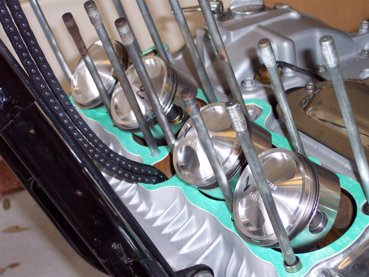 This
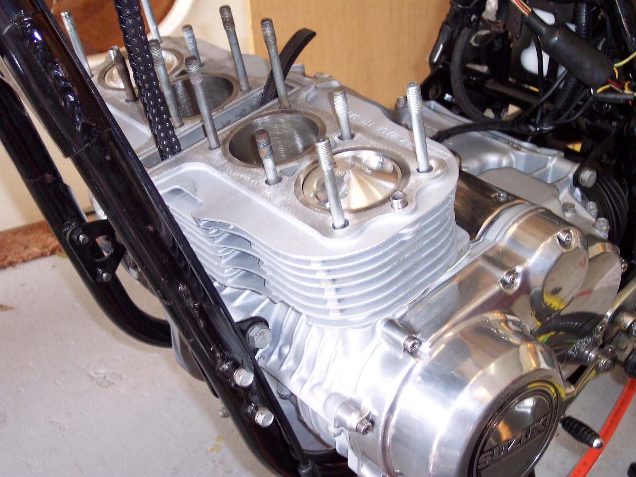
is a definite thing of beauty! The base gasket under the block is green.
You can see the new cam chain still suspended, and the four Wiseco 1085mm forged
pistons have been pinned to the connecting rods. O-rings have been
installed on the rear outside studs since they also serve as oil passages, and
the guide dowel-pins, one of which you can see to the left, toward the bottom of
the picture. They are used to properly align the cylinder block with the
engine case.
This
is a definite thing of beauty! The base gasket under the block is green.
You can see the new cam chain still suspended, and the four Wiseco 1085mm forged
pistons have been pinned to the connecting rods. O-rings have been
installed on the rear outside studs since they also serve as oil passages, and
the guide dowel-pins, one of which you can see to the left, toward the bottom of
the picture. They are used to properly align the cylinder block with the
engine case.
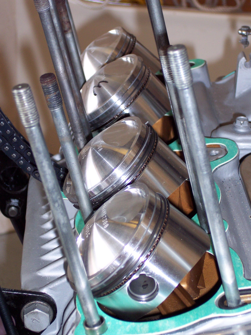
Another shot to the right shows more clearly the oval 0-rings that are on the rear outside studs...the gasket is specially cuts to receive them. The are very important since the oil is forced up this channel to the head. The oil is under pressure, of course, and the 0-rings seal the oil passage between the engine case and the base of the cylinder block. You will also notice that the tops of the pistons are numbered with a grease pencil. During the boring of the cylinders, each cylinder was measured and bored to match the specific diameter of the particular piston that was going into that cylinder. Numbering them ensures that when I install the pistons that each one will match with it's assigned cylinder when the block is installed.
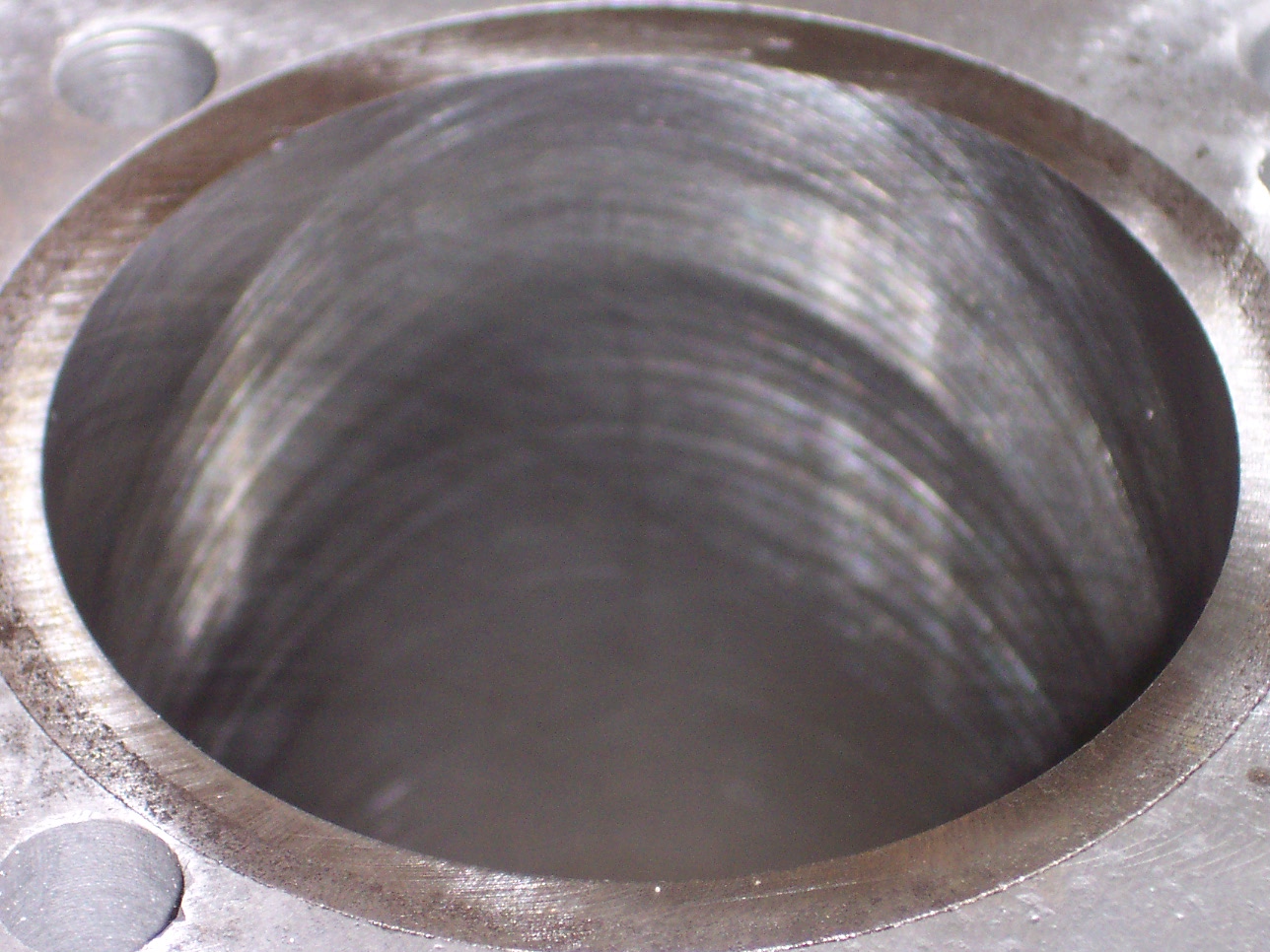
You can see in the picture on the left, one of the cylinders after being bored out to match the piston diameter. The swirl marks are the deliberate honing pattern necessary for the piston rings to seal efficiently when running. A special grit and stone hone is used to make sure that the cylinder surface is not so smooth that the rings will be unable to "seat". This is necessary to provide a good seal, the rings will "wear" into the cylinder wall, matching very closely, thus making an excellent seal for combustion to take place.
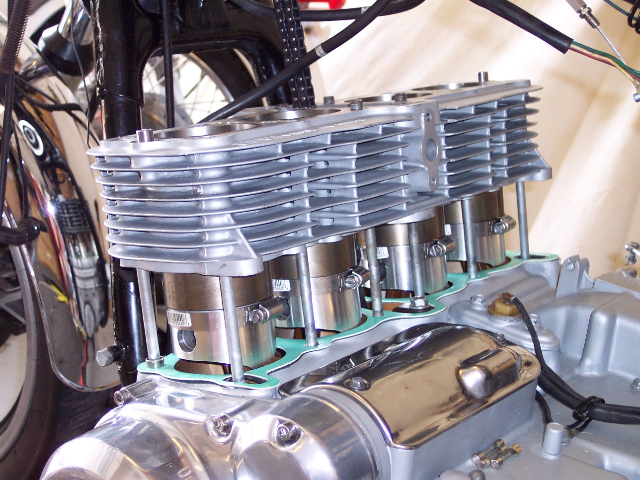
Here you can see the cylinder block being installed. You can see four hose clamps around each piston. This is to "compress" the rings against the pistons so they'll slide into the cylinder bores with damage to the rings themselves. The bottom ring, or oil ring, is actually three pieces, and are quite delicate. The make sure that one or more the them are not damaged, it's really suggested to use a ring compressor, or in this case, four cheap hose clamps, which work just as well. Being very careful to gently tap the block onto the pistons, once the rings are well inside the cylinders, the hose clamps are removed, and the block is slide on all the way to meet the base gasket.
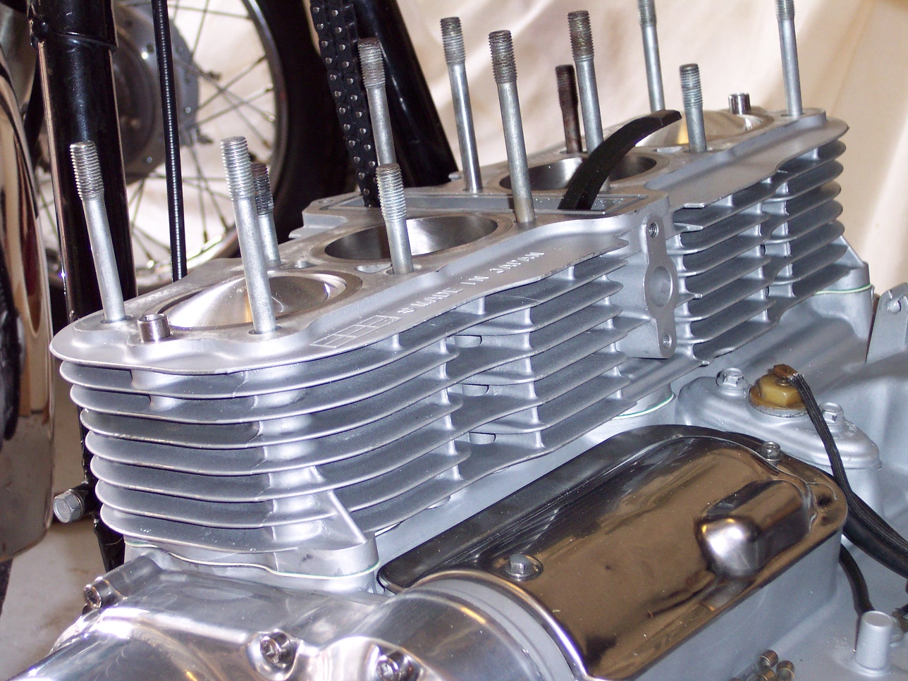
Cylinder block is on now, and the rear cam chain guide is installed. That's the black curved piece you see sticking out the top of the block. Not much else to do once this is on, except to install the head. You saw that earlier. It's been completely reworked, new valve seats ground, valves were refaced, guides were checked, and replaced if necessary, and new valve seals installed. Below is just another angle...you can see the two outside pistons, and in the center holes you can clearly see the hone marks.
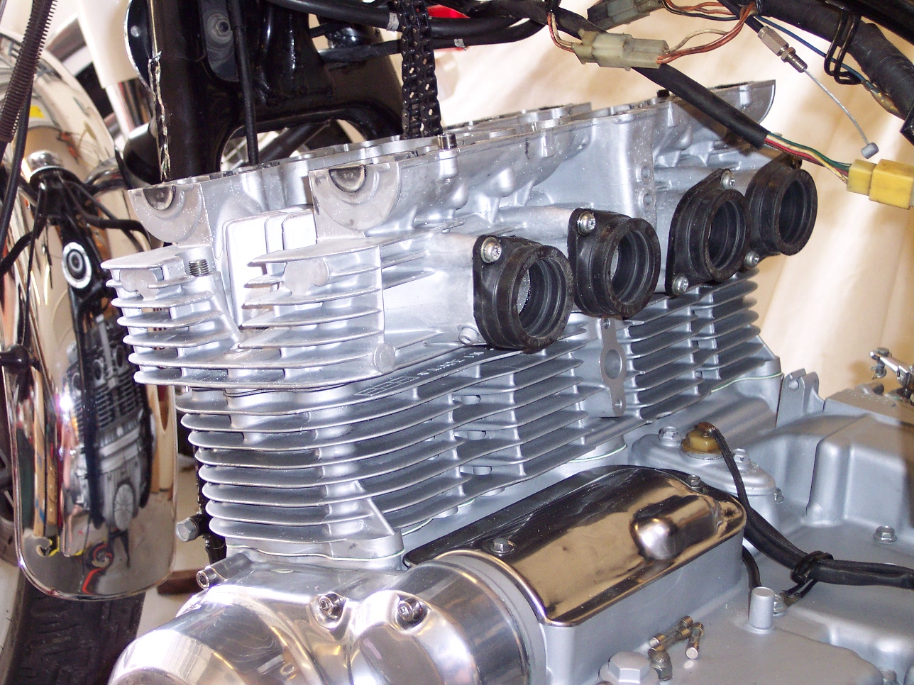
You can see to the left what it looks like after the head is installed on the block. The cam chain has been threaded through the center to drive the cams. You can also note the rubber carburetor intake manifolds have already been installed on the head. It's much easier to do it with the head on the bench rather than in the frame of the bike. The front cam chain guide goes in at this point, and then the intake and exhaust cams are installed, and the alignment marks lined up properly to ensure correct valve timing.
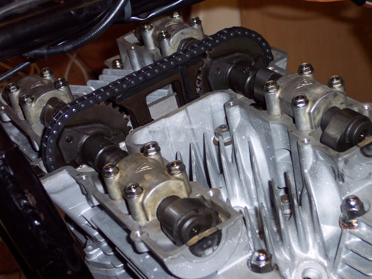
Now you can see both cams installed, with the cam chain and center cam chain guide between the two gears. The cams have been torqued properly, and the register marks lined up as they should be to make sure the intake and exhaust valves open and close as they should.
Things are moving along now!
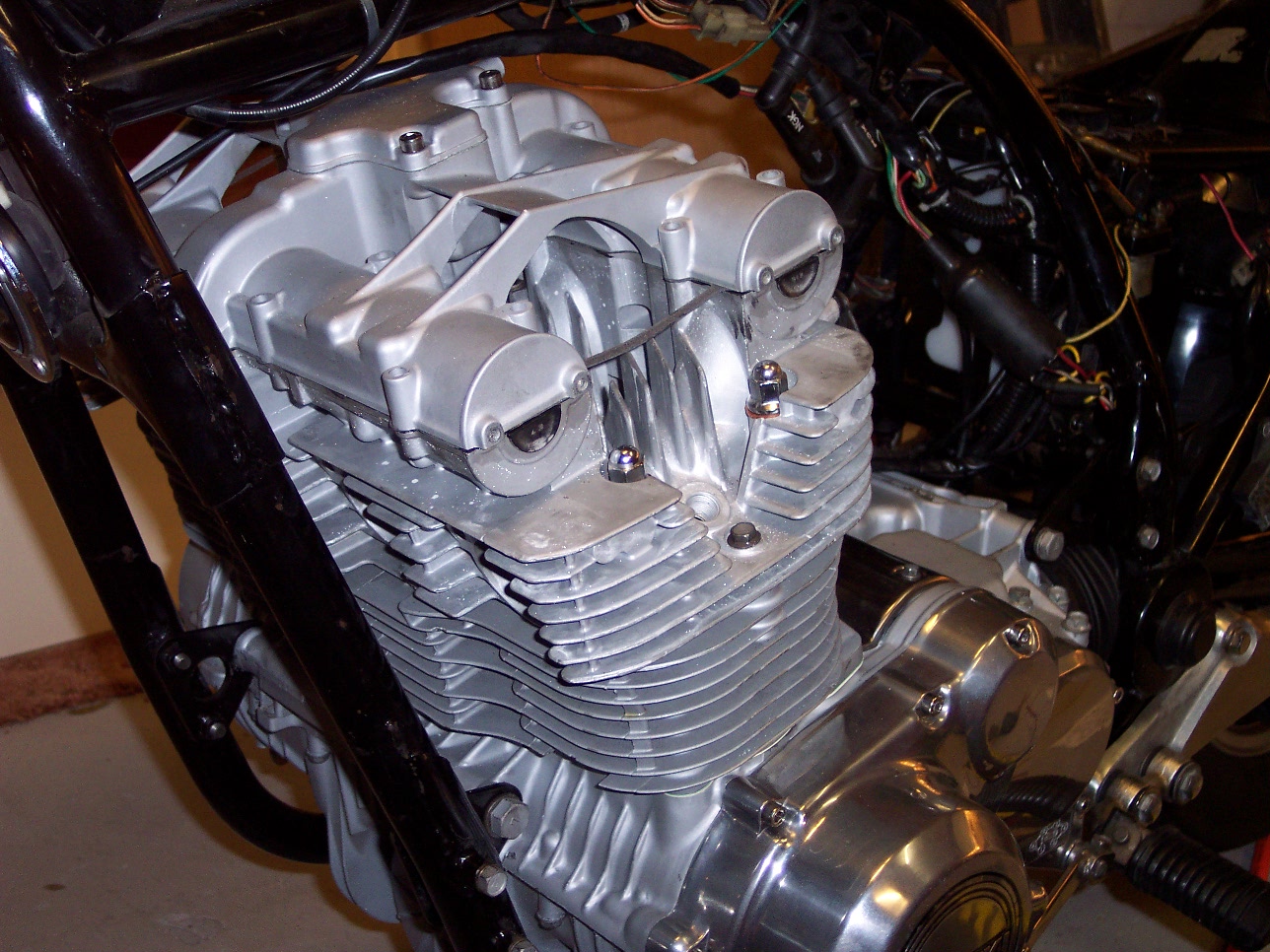
Below, you can see that I've installed the cam cover and gasket, and on top of that is the breather cover, and breather tube, which will eventually connect to the air intake box.
The spark plugs are in, the wires connected, and the carburetors are installed next.
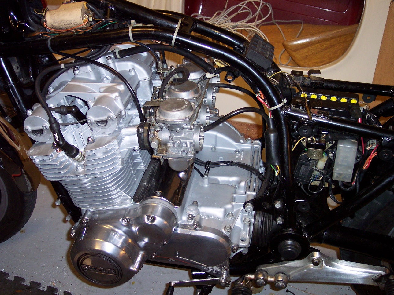
The airbox goes on next. This is where the air filter is contained, and it also has the chrome trim on each side.
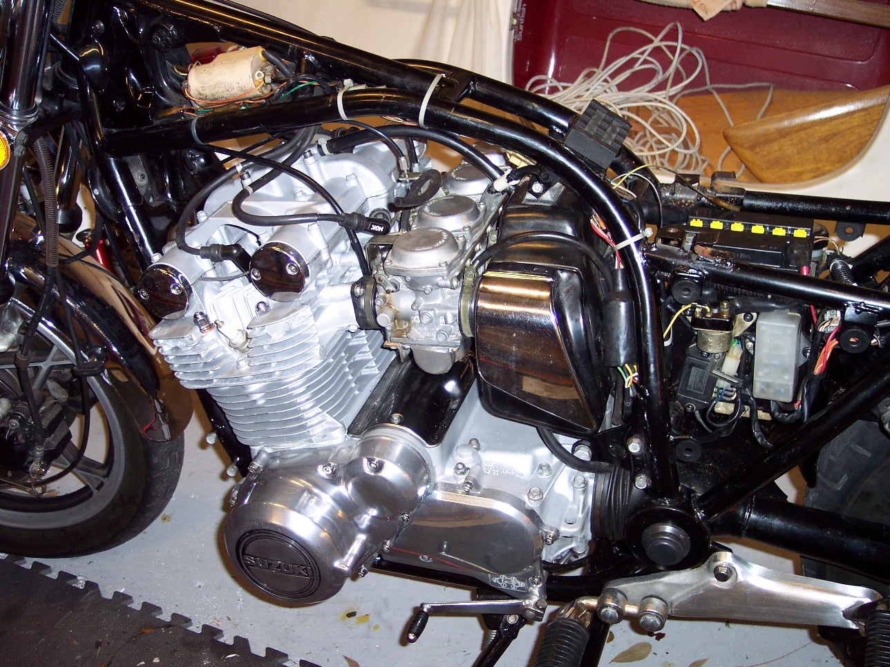
It's pretty close now..Tighten all the clamps, route the fuel lines, overflow lines, air-breather line, and make sure all the electical connections are made. At this point, I ran into a problem with the electronics. It seems there is more than one connection to ground on this bike. I had to trace, retrace, and recheck all the grounds to make sure they were all connected to where they needed to be. It took a couple of hours from where you see the picture to the left of here, to where I was able to go ahead and install the gas tank and seat, as you see below.
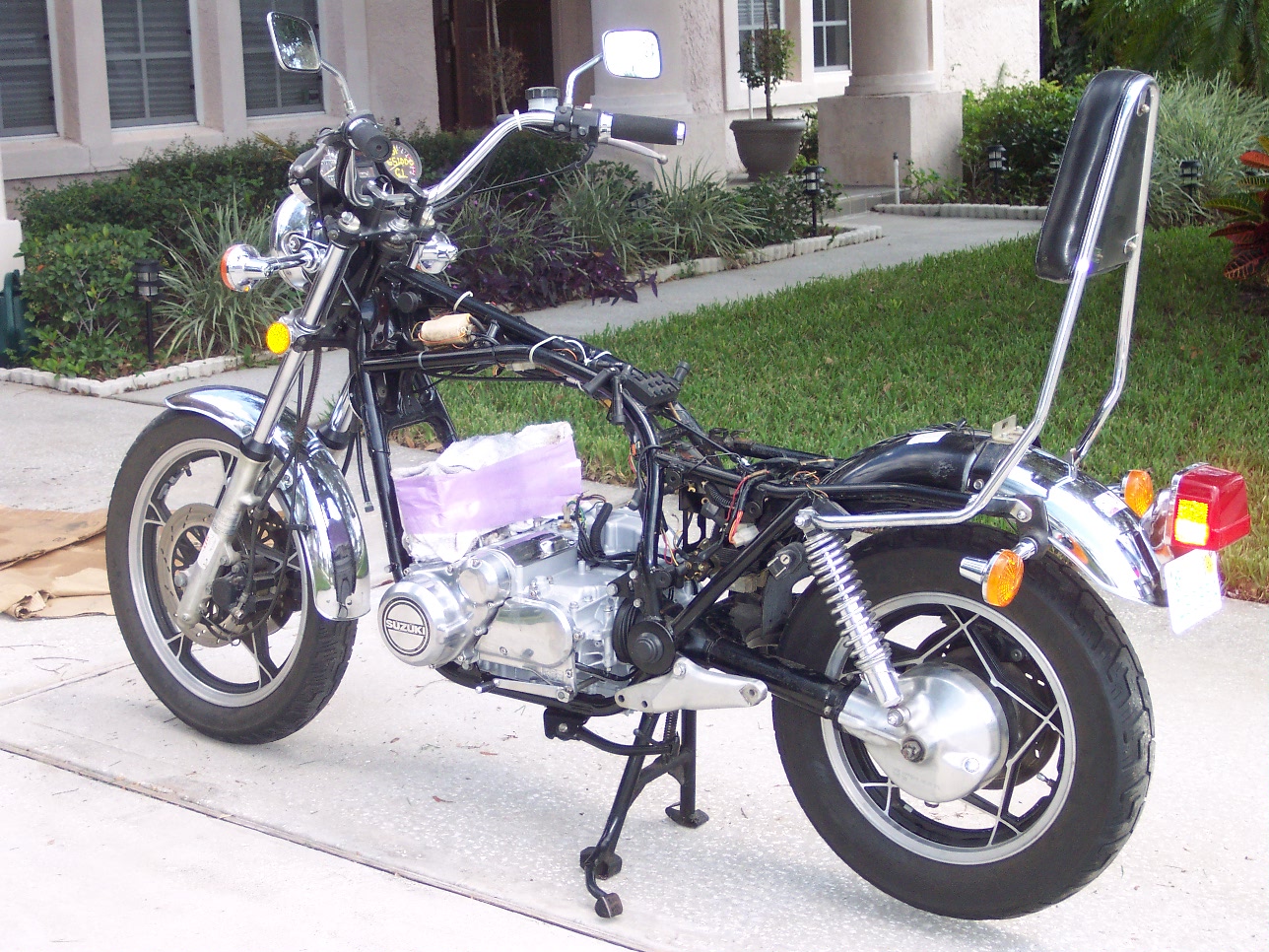
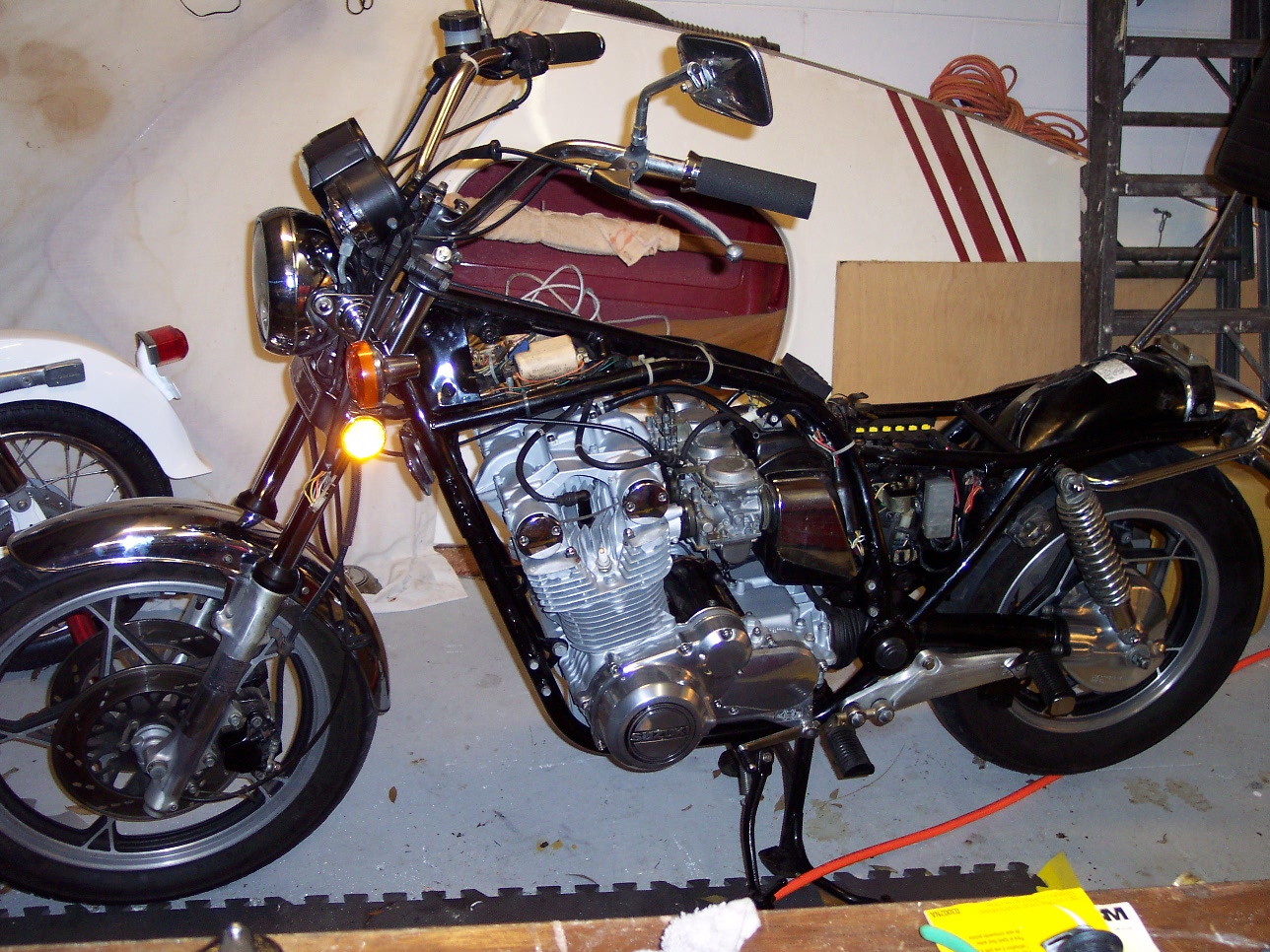
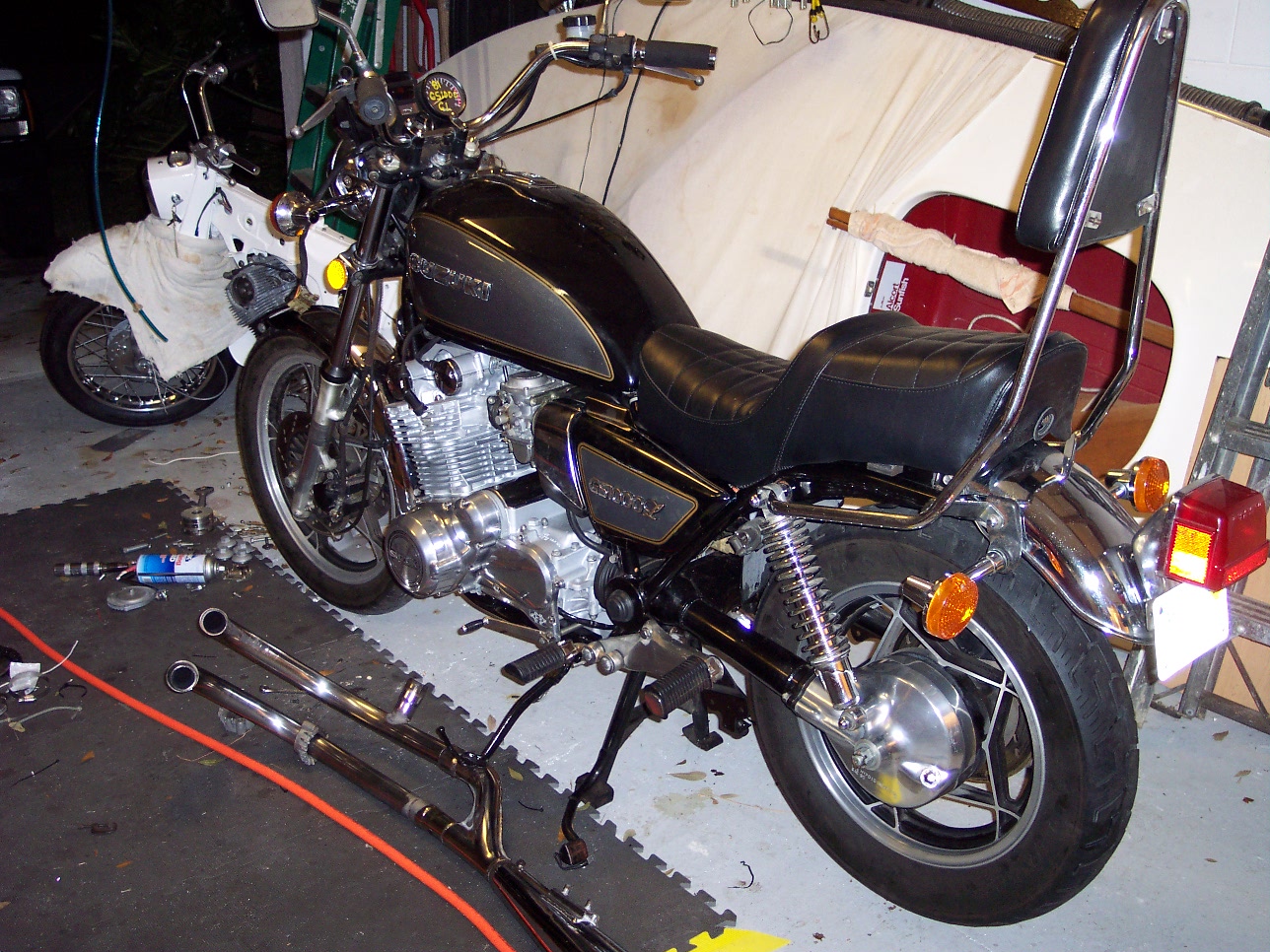
 Only
a few things left to do now. Have to make sure the ignition timing is
close, and install the exhaust pipes, mufflers, etcetera. You can see the
header pipes lying on the ground behind the bike. But it's late in the
evening now, and that's a project for tomorrow.
Only
a few things left to do now. Have to make sure the ignition timing is
close, and install the exhaust pipes, mufflers, etcetera. You can see the
header pipes lying on the ground behind the bike. But it's late in the
evening now, and that's a project for tomorrow.
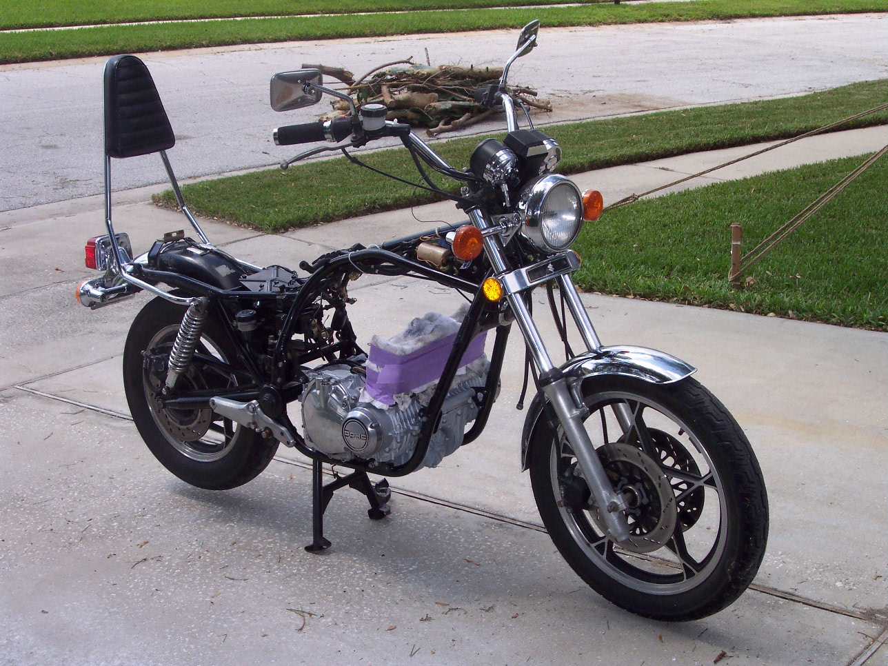
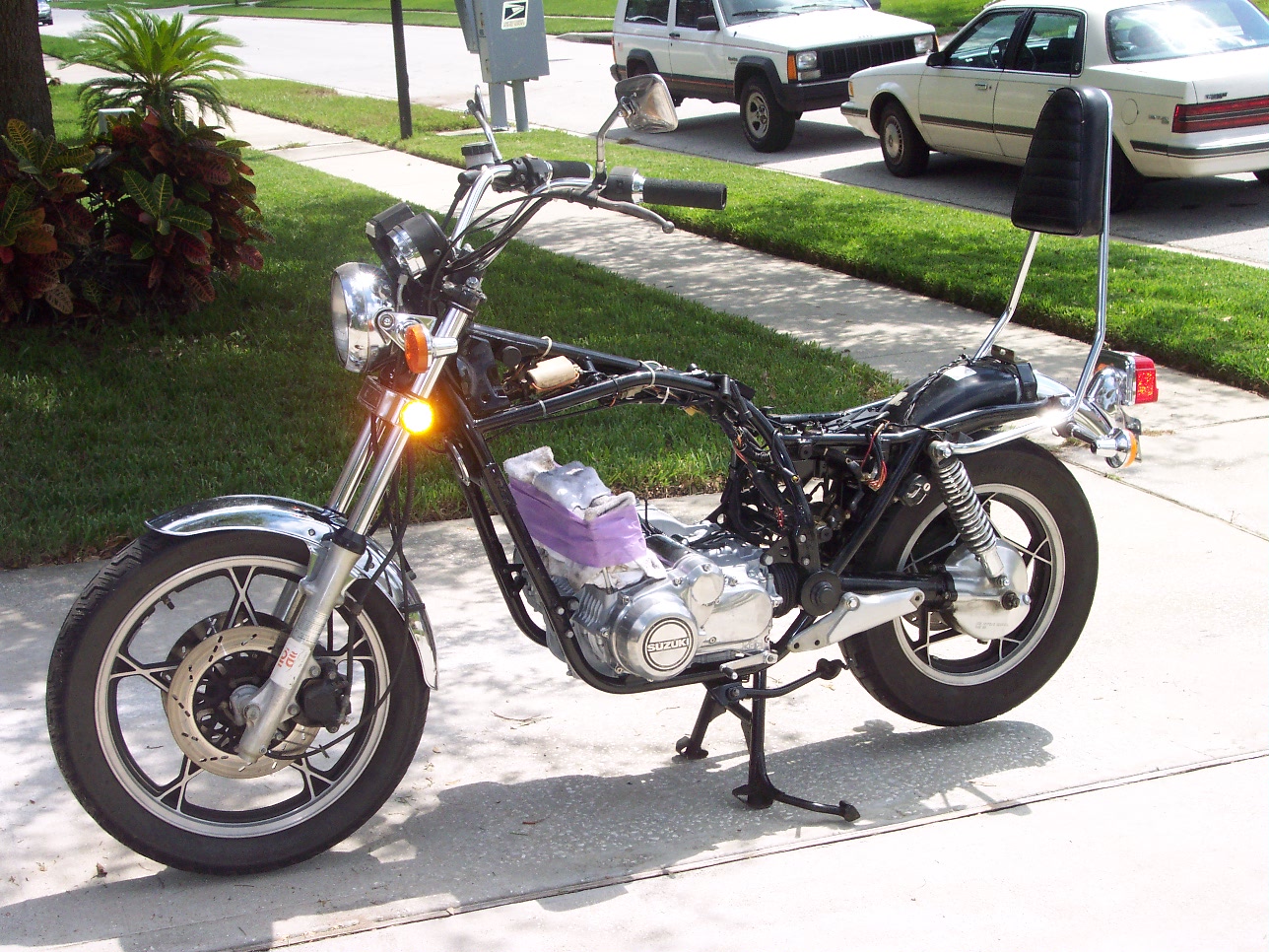
Looks more like a motorcycle now...doesn't it?
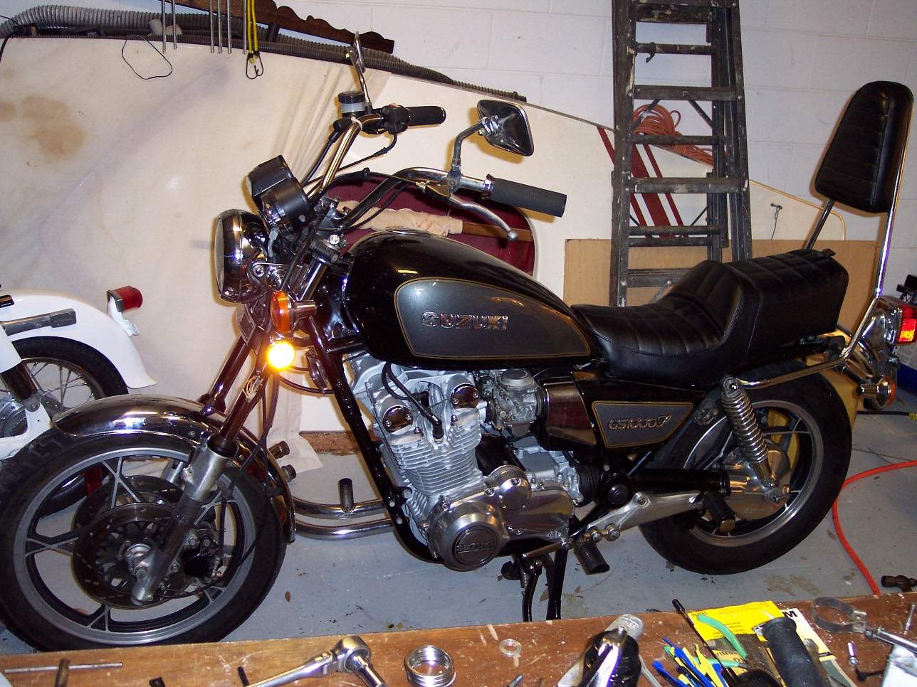
The next day came, and I got the exhaust pipes and mufflers installed. It runs! The carburetors, though having been completely rebuilt, were close enough that the engine runs rather smoothly, at least enough to take her out and put a few miles on!
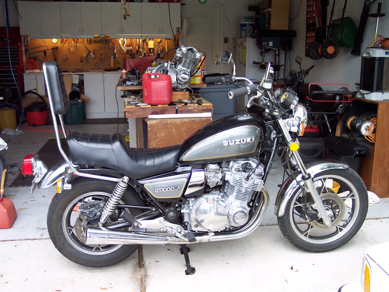
So now, it's time to put some miles on the bike, break it in, and get to the 600 mile point for the first oil change and checkup. The valve clearances will be checked and adjusted, the carburetors will be synchronized, and any other tune-up parameters will be taken care of.
A 4-into-1 exhaust is next to go on, and the air filter will be upgraded to a K&N performance filter. This will require a DynoJet Stage 1&3 kit to be installed.
This GS1000GL originally had 997 cubic centimeters displacement at 9.5 to 1 compression, but now has 1085 cc's with 10.25 to 1 compression. The carburetor kit, filter, and header should really wake this engine up!