 After
rebuilding the engine, it didn't run very good...missing, hesitating, popping,
and backfiring. I had already replaced the diaphragms based on the advice
of the motorcycle shop mechanic, but that apparently wasn't the whole problem.
As I thought about it, the bike sat for long periods of time where the
fuel in the float bowls evaporated, probably leaving gum and varnish to plug up
the fuel passages.
After
rebuilding the engine, it didn't run very good...missing, hesitating, popping,
and backfiring. I had already replaced the diaphragms based on the advice
of the motorcycle shop mechanic, but that apparently wasn't the whole problem.
As I thought about it, the bike sat for long periods of time where the
fuel in the float bowls evaporated, probably leaving gum and varnish to plug up
the fuel passages.
Sure enough, while the choke was on, I started and ran the motor for just a
few seconds, and then turned it off. Checking the header pipes I found
that the two outside pipes were dead cold, while the two inner exhaust pipes
were hot to the touch! That told me that the choke circuit in at least two
of the carbs wasn't working.
So the next thing to do is to disassemble, clean, and rebuild the
carburetors.
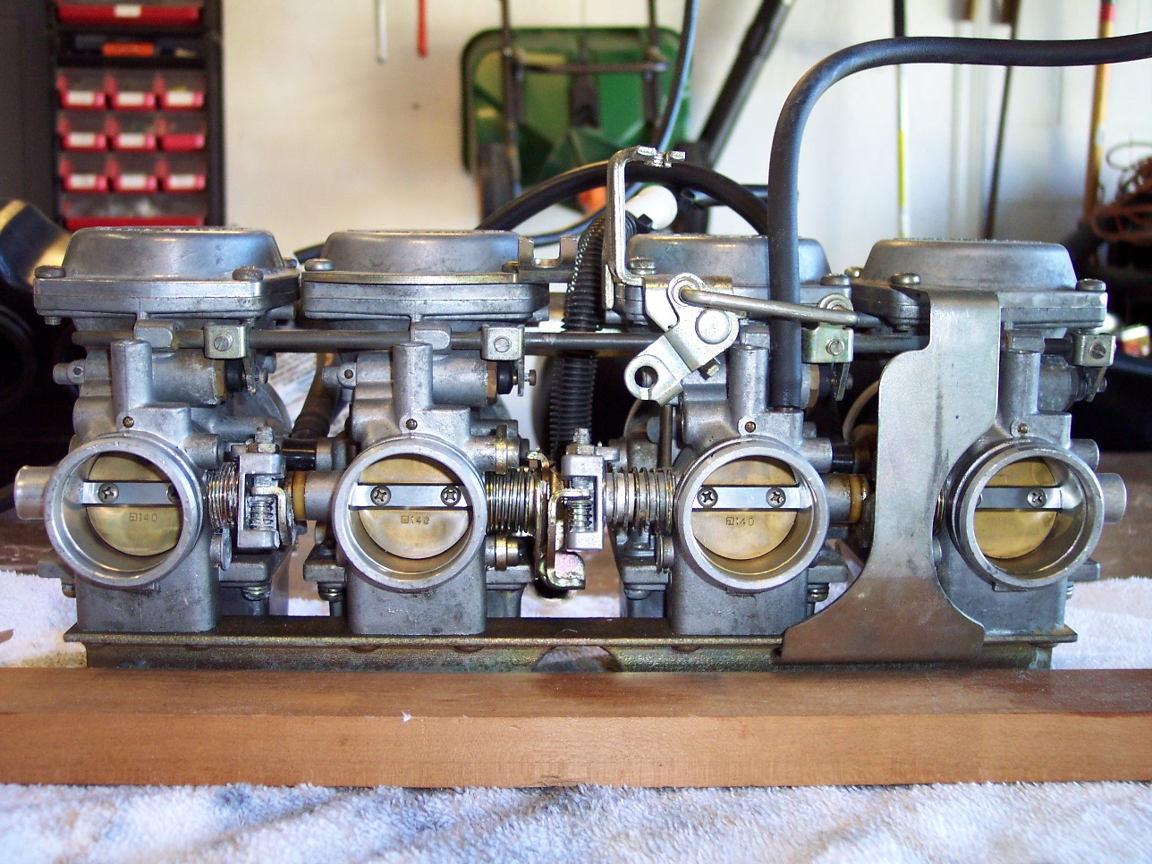
 The
linkage connecting the four carburetors together is complex and intricate.
Lots of pictures at this point will be helpful in ensuring that I'm able to get
them back together again.
The
linkage connecting the four carburetors together is complex and intricate.
Lots of pictures at this point will be helpful in ensuring that I'm able to get
them back together again.
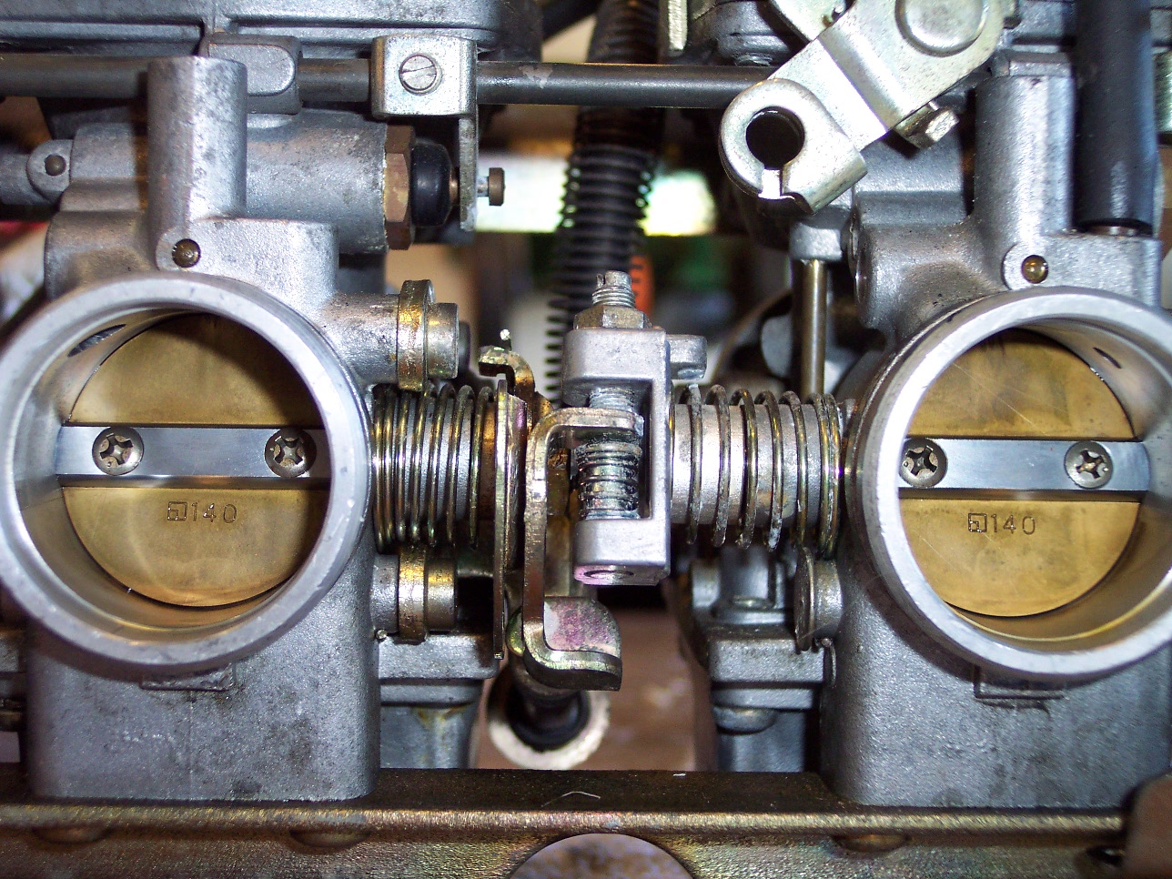
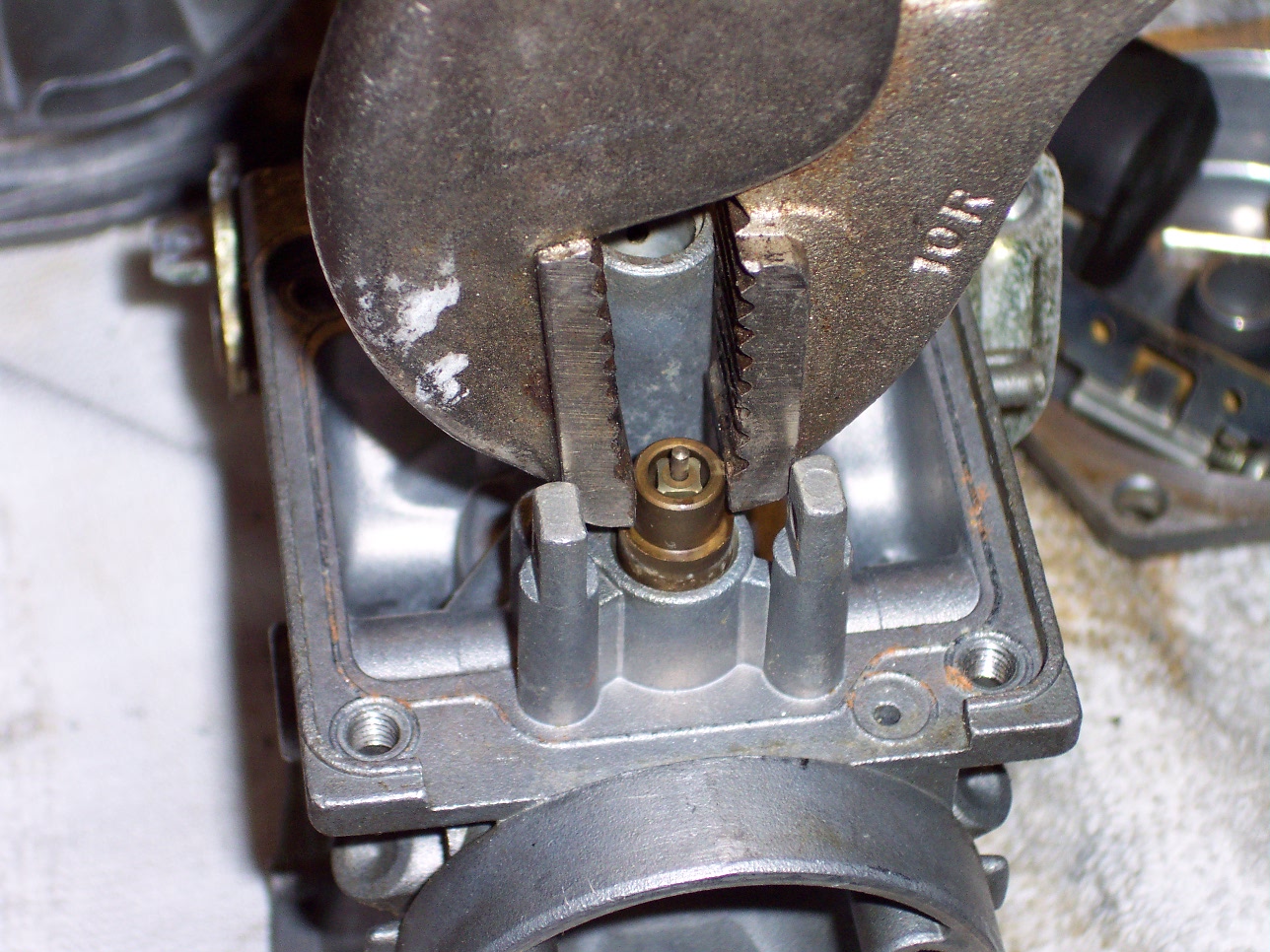
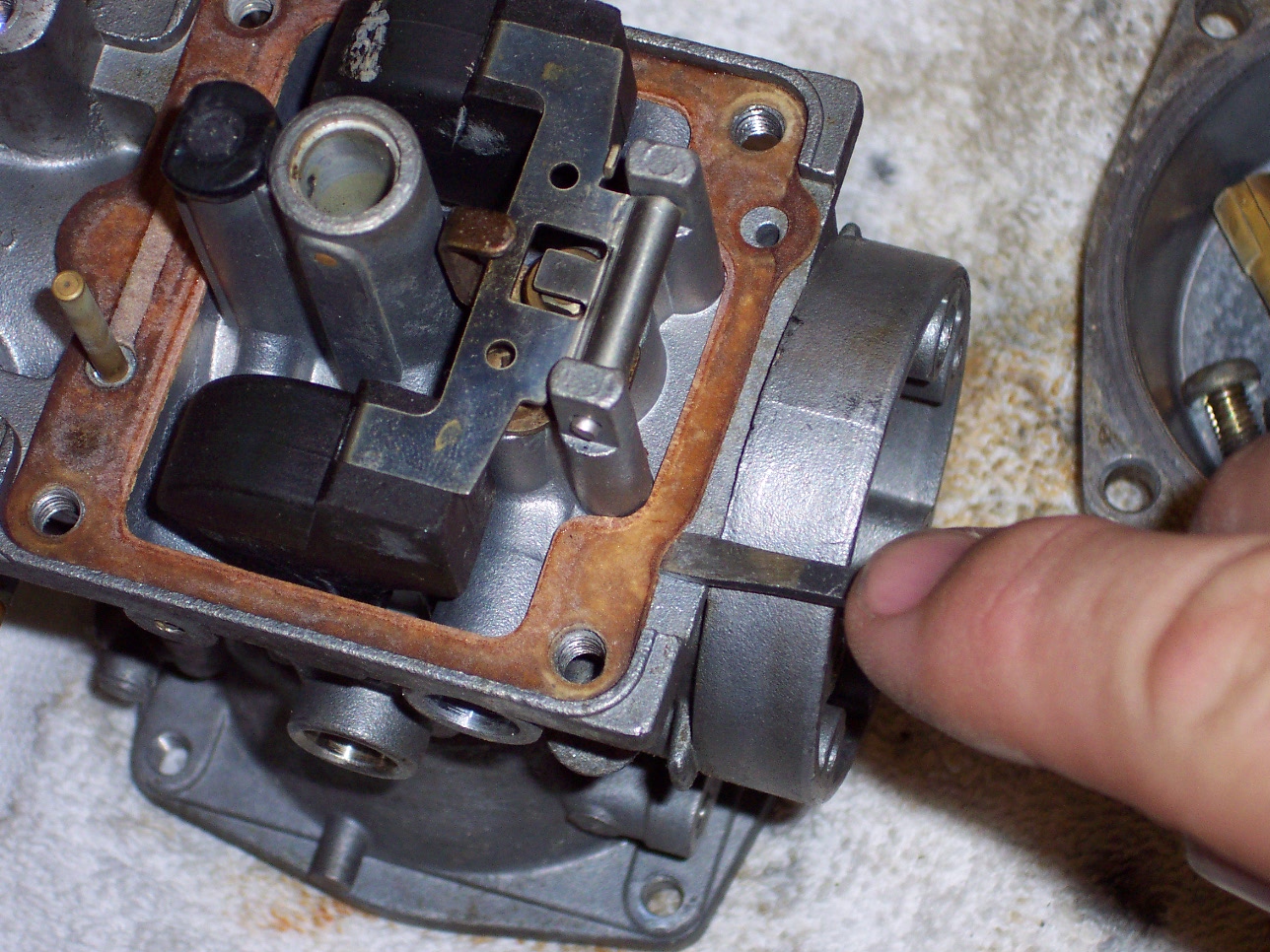
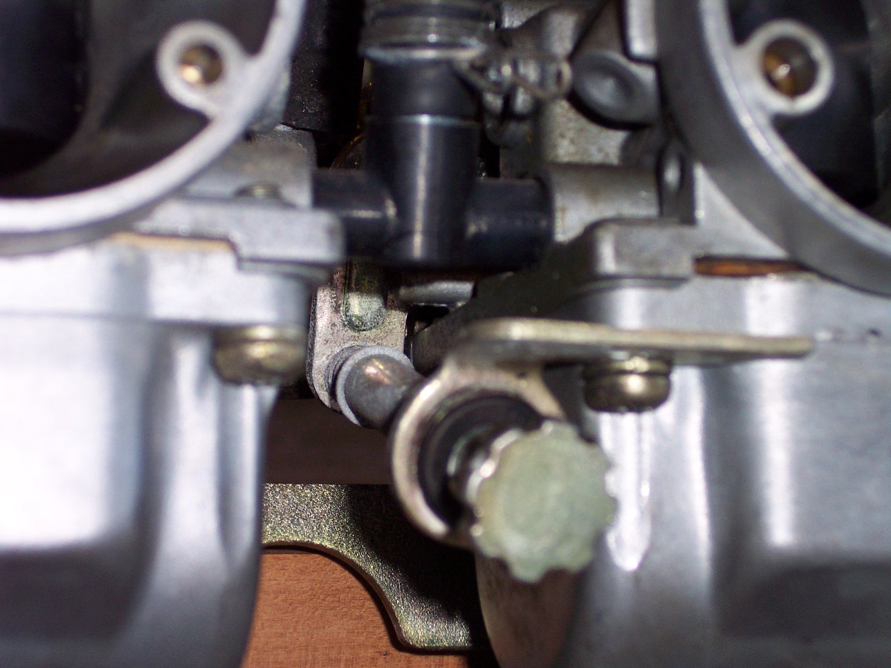
This is on of those pictures showing the detail of the throttle control that
opens the butterfly valves. The adjustment you see is to balance one of
the four carburetors, or to synchronize them, so they all pull the same level of
vacuum. This ensures a smooth, balanced-running engine.
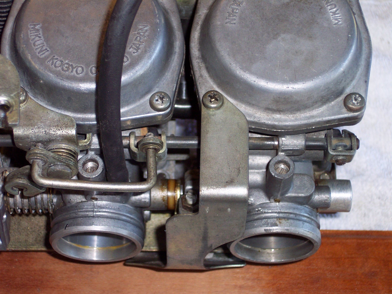
This picture shows where the fuel enters one of the carburetors.
This carburetor is unique, in that it is the only one with this fuel intake.
The other carburetors are connected through a "fuel rail" to this carburetor.
You can see the carb on the far right, it does not have a fuel inlet at all.
As it turns out, each of the four carburetors on this bike is unique to itself,
so in order to replace any of them requires one to note whether it's the left
inside, left outside, right inside, or right outside. Makes for an
expensive setup.
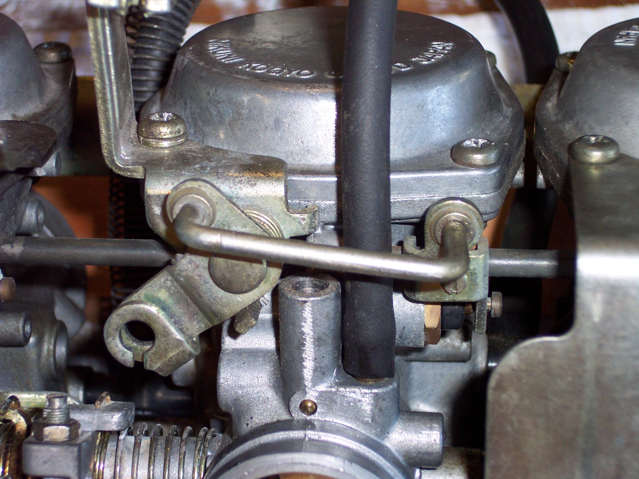
Here, you can see the choke actuator. This linkage extends to all four
carburetors by the black horizontal bars about mid-picture. As the choke
is engaged, this linkage pushes the bar to the right as you look at this
picture.
The choke itself can be seen on this carburetor directly below the right side
of the u-shaped linkage. It's the black piece on the brass hex nut.
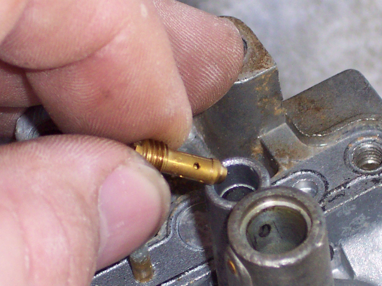
The choke on these carburetors doesn't close a butterfly as you might be used
to seeing on a car. It opens a separate fuel circuit in the carburetor
that pulls fuel directly from the float chamber, creating a richer fuel mixture
that the engine requires when it's cold. Here, you can see the plunger
that moves in and out...it has a bit of corrosion on it.
Left, the carburetors are upside-down, and I've removed the sediment bowl
from the carb on the far right. You can see the idle adjustment that is
situated between the two center carburetors, toward the top of the photo.
With the sediment bowl removed, you can the Main Jet in the center, between
the floats. It will be replaced.
Directly behind it is the Pilot Jet. It's actually under a black rubber plug.
The plug is a replaceable item that comes in the carburetor rebuild kits.
You can see the black plug in the lower left picture. The sediment bowl
has a protrusion that retains the plug, thus the indent that you see.
The lower left shows the removal of the float and needle valve. It's in
pretty solid so I'm using vice grips. The whole assembly is going to be
replaced so I'm not worried about deforming the unit.
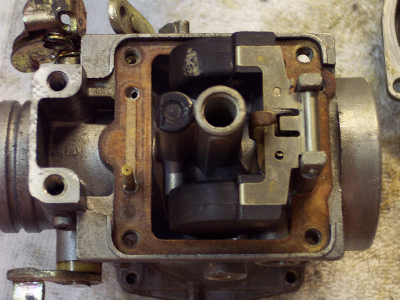
The large hole you see toward the bottom of the picture on the right is where
the Main Jet resides. Directly below, protruding through a hole in the gasket, is a tube that
extends into the float chamber...this tube is part of the choke circuit, and has
a very tiny hole in the end to meter fuel past the normal running circuit, and
direct it directly into the engine. If this tube becomes plugged, the choke becomes disabled.
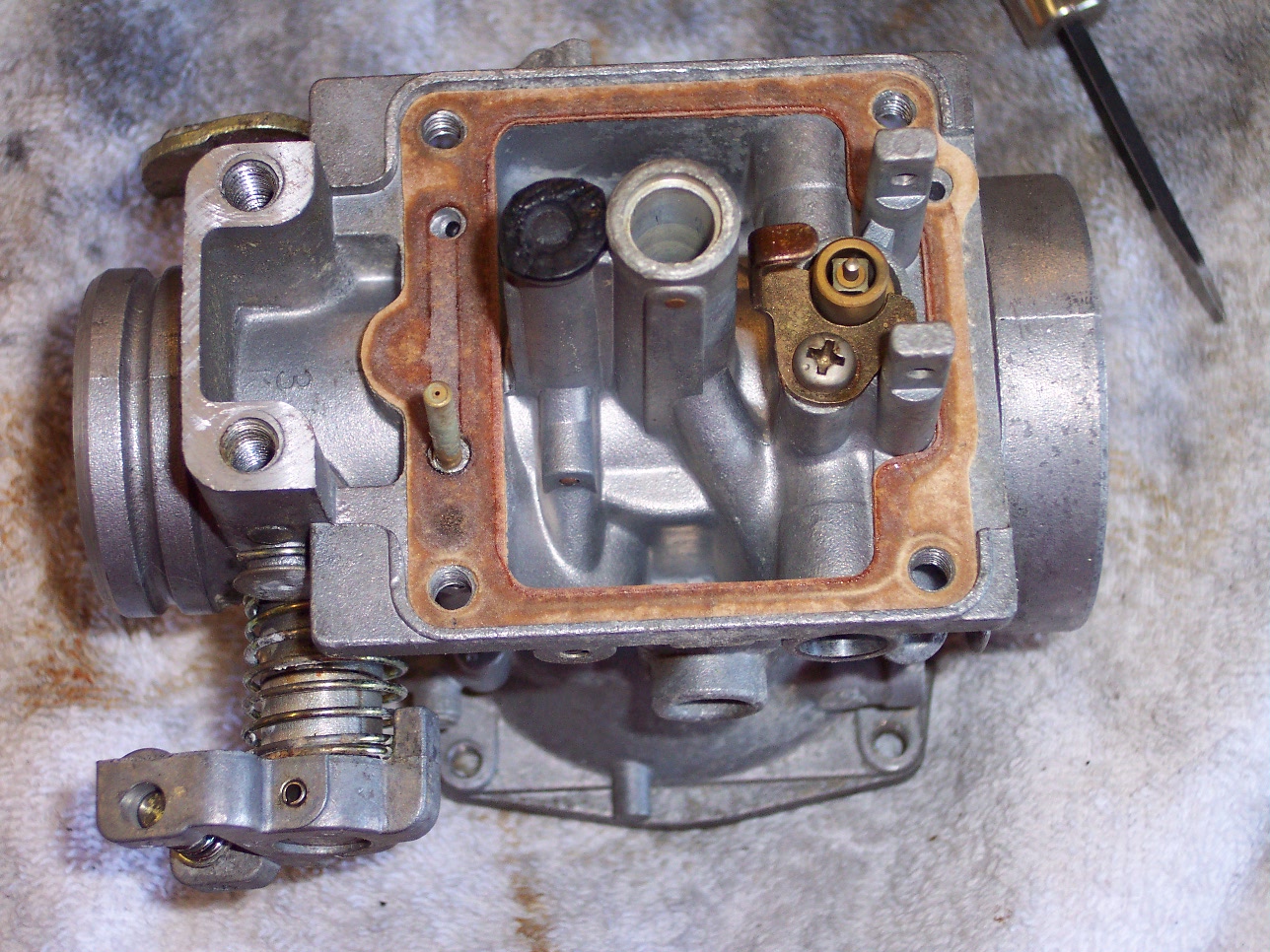
Above right, you can see me prying and working the gasket off the carburetor
body. Being careful not to gouge the aluminum, it's pretty soft, and any
deformations will prevent a good seal, and thus air leaks.
This is the pilot jet that lives under the black rubber plug. The plug
just lifts right out, and the jet unscrews.
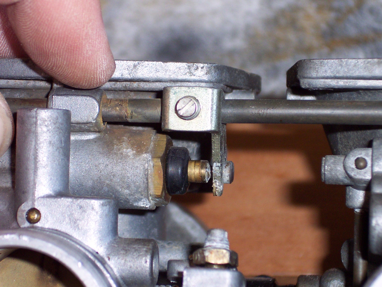
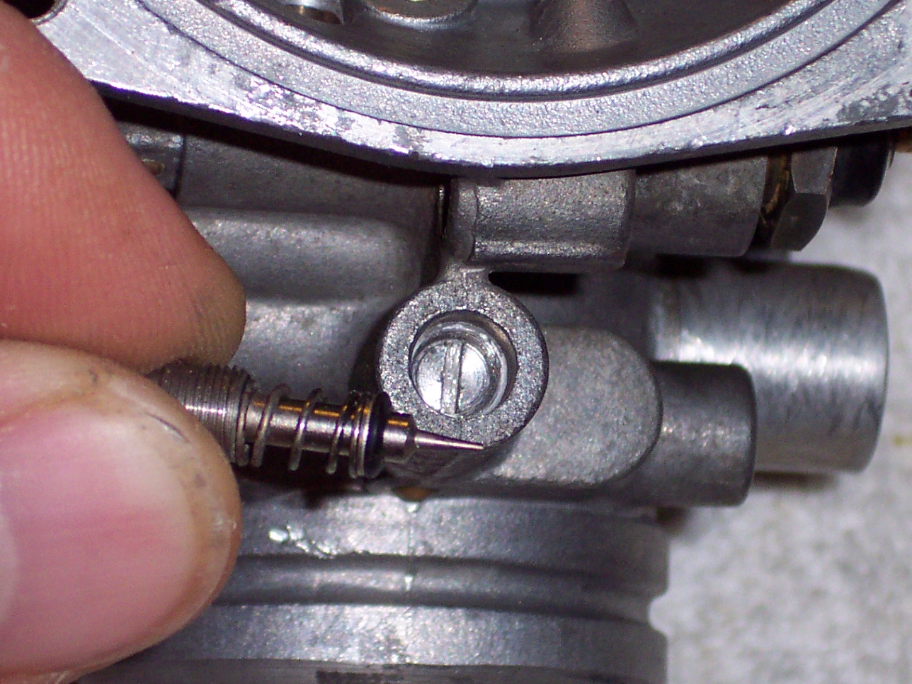
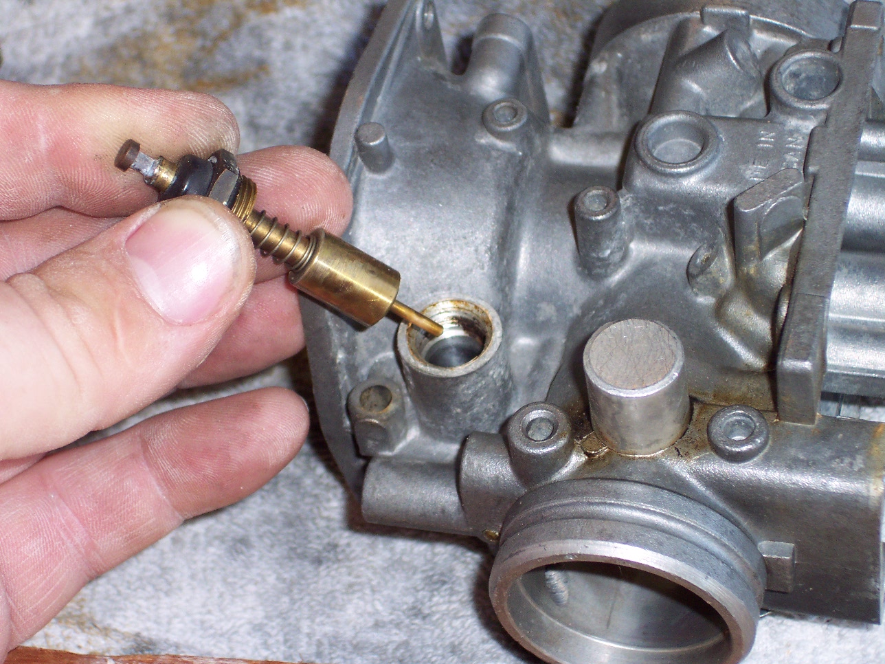 Here, you can see the plunger mechanism that is the choke. What
you see in my hand is the choke rod that slides in and out to open and close the
choke circuit. Each carburetor has one of these. The only
replaceable part on this item is the o-ring used to seal the hex nut (between my
fingers), so air doesn't leak into the system.
Here, you can see the plunger mechanism that is the choke. What
you see in my hand is the choke rod that slides in and out to open and close the
choke circuit. Each carburetor has one of these. The only
replaceable part on this item is the o-ring used to seal the hex nut (between my
fingers), so air doesn't leak into the system.
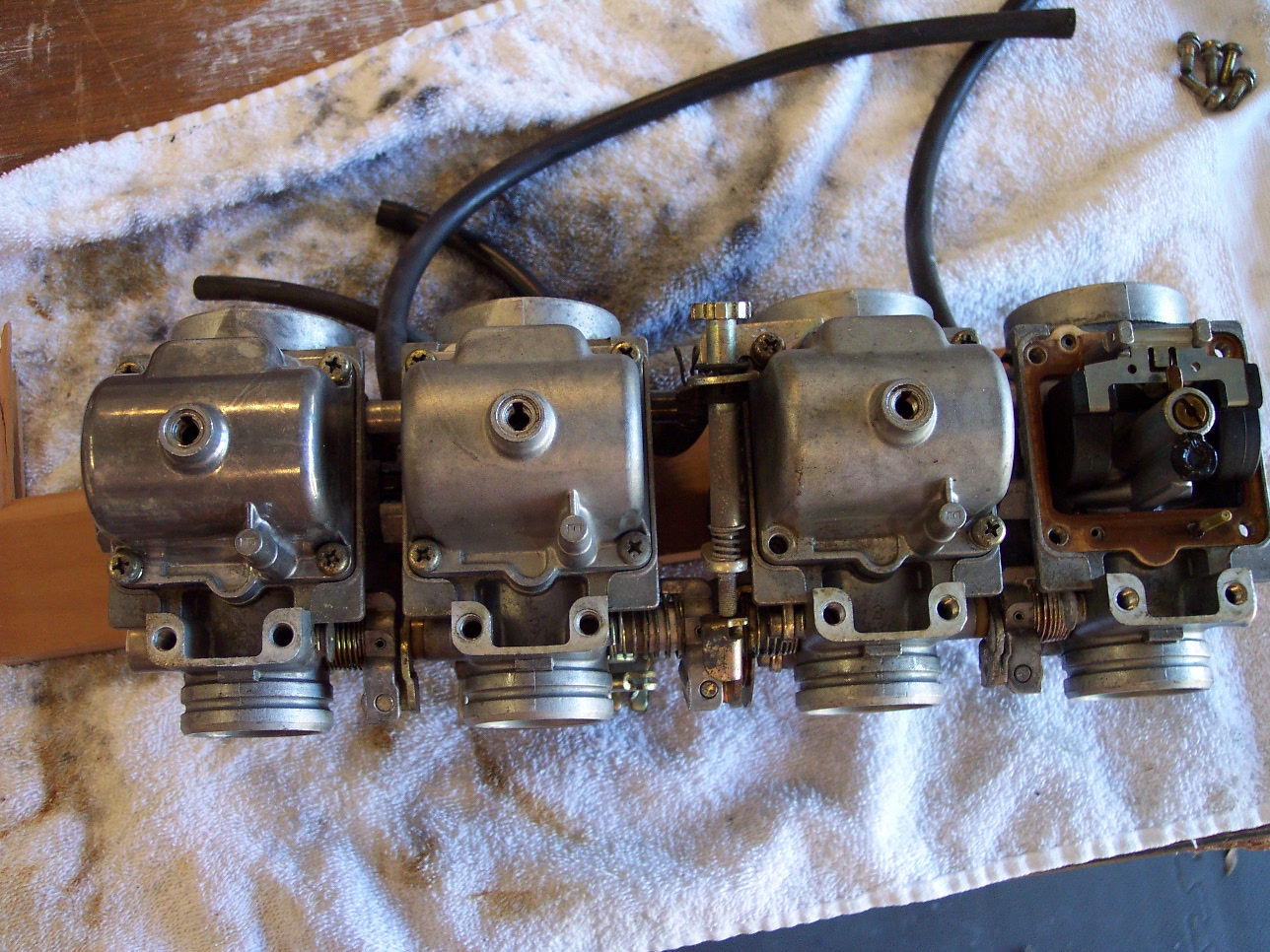
Here you can see all four carburetors at various stages of disassembly.
The floats can easily be seen in the bottom of each carburetor, they are the
black circular pairs. Between each carburetor on the towel you can see
black "T" connectors...these are the fuel overflow tubes. They connect
between all four carburetors, and if the needle valves fail to close and turn
off the fuel supply, these will direct the fuel through the lines and onto the
ground, hopefully preventing contamination of the engine oil.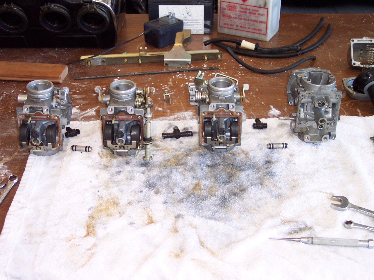
The two silver bullet-shaped items on either side of the two inside carburetors are
part of the fuel rail I mentioned earlier...they distribute fuel from the gas
tank to the fuel bowl of each carburetor.
Another shot, to the right, of the bottom of one of the carburetors.
The needle valve is to the right, held in by a retainer bracket that is in turn
held by a screw. The black plug to the left covers the Pilot Jet, which
you saw my withdraw above.
On the top of each carburetor, on the end of the carburetor that faces the
intakes of the engine, is a small needle valve...this is the Fuel-Mixture
adjustment. On my bike, each was adjusted to 3 1/8 turns out from the
seat.
You can see that there is a spring, a washer, and a really tiny black o-ring.
these replacement parts are included in the carburetor rebuild kits. Good
thing too, because there was no way to find an o-ring this tiny!
Once all the parts and gaskets are removed, the carburetor bodies are soaked
in a can of Gunk parts cleaner. Gunk makes an excellent
carburetor and parts cleaner that comes in a 3 lb. coffee can with a lid and
strainer/small parts basket. This stuff is pretty potent, and after each
carburetor soaks in the cleaner for a couple hours, I use the air compressor to
blow out each fuel passage and orifice. It does a great job! The
aluminum cleans up quite a bit, not quite like new, but pretty close!
After replacing the consumable parts, reassembly of the carburetors meant
checking the photos I took earlier, most of which are listed above in this
sequence. A comparison made sure that they went together in the same
manner in which they came apart.
The good news is, they indeed went together as they were supposed to, and I
put them back on the bike, and not only did it start right up, but it idles
better, the choke circuit is performing admirably, and the synchronization
between all the carburetors is pretty close. At least I'm able to run the
bike around town, and it's really running pretty good.
Next.